In May of 2025 I developed an interest for xenon flash lamps after taking apart an old broken camera flash. This inspired me to build my own flash lamp driver circuit from scratch. The end goal of this project was to build a strobe light for the band that I play in which could be triggered using the bass drum.
Hardware

I decided to use a 500W xenon lamp pictured to the right. It consists of a borosilicate glass tube with a tungsten anode and cathode in each end, along with a nichrome trigger wire wrapped around the outside. To fire a lamp like this one a capacitor is connected across the two electrodes and a high voltage pulse is sent between the trigger wire and one of the electrodes (this is known as "external triggering"). This is able to ionize the gas inside the tube capacitively, allowing it to conduct the relatively low voltage from the capacitors.
Proof of Concept
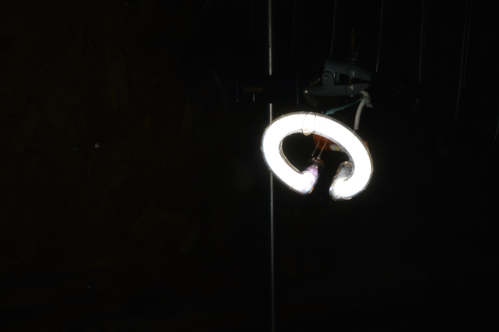
Before designing the final circuit I decided to experiment with the flash lamp from the camera flash to test the premise of the design. A single stage voltage multiplier circuit was used to charge the capacitor (taken from the original flash circuit) with mains power (120V AC). For the trigger circuit I reused a high voltage power supply that I bought online in the past for a sodium vapour lamp ballast. While it was rather unreliable (likely due to the trigger circuit not supplying high enough voltage) this set-up was able to flash the lamp, meaning that I was ready to move on to designing the circuit for a larger lamp.
The Trigger Circuit
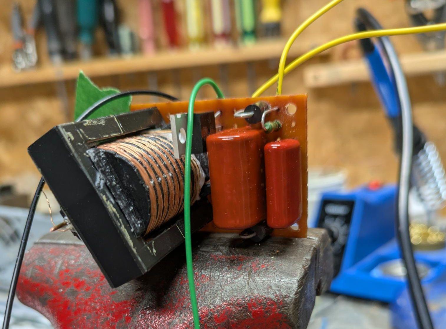
The first part of the project I decided to work on was the trigger circuit as this was necessary for testing other parts. The trigger circuit must be able to provide a fast high voltage pulse in the 10kV range. Another requirement was that it could eventually be controlled using a Raspberry Pi.
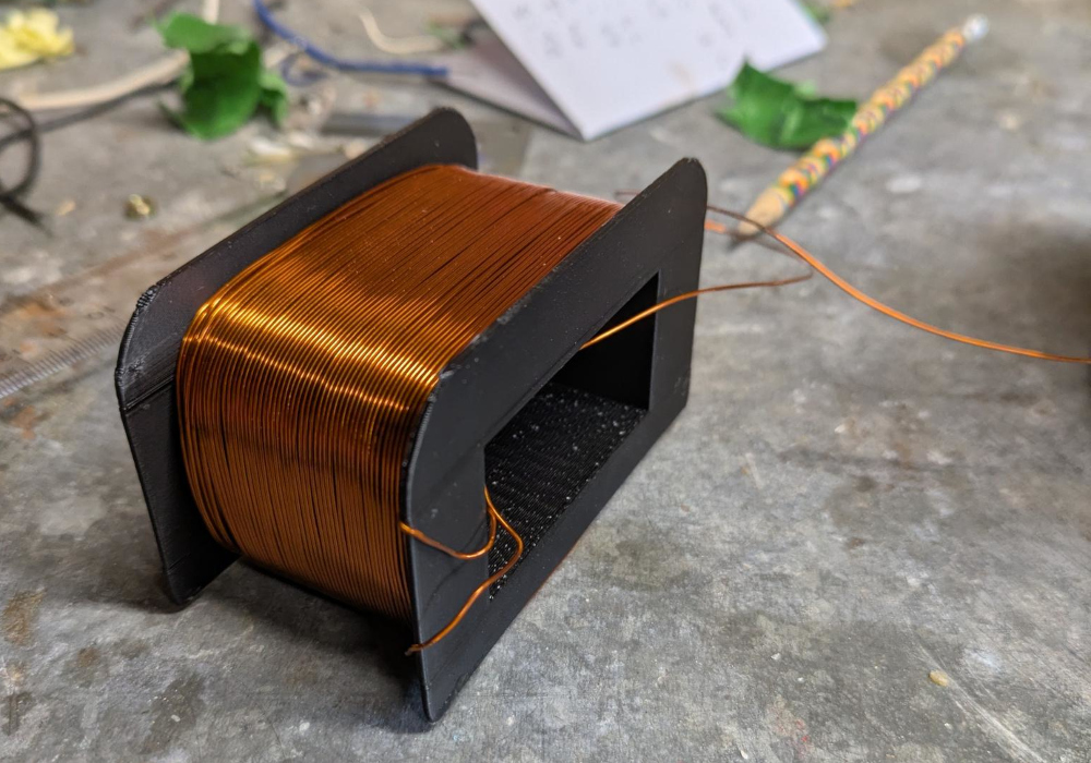
It was decided that the high voltage pulse would be created by discharging a capacitor through the primary coil of a transformer with a high winding ratio. Because the transformer would be operating at a high frequency as the capacitor resonated with the primary, a ferrite core was chosen. The core was taken from an old computer power supply. Next a bobbin to hold the windings was 3D printed. It featured fins to separate the secondary into 7 different sections, as to prevent arcing. After winding, the bobbin was potted in epoxy for extra insulation and cured under vacuum. The final transformer featured 25 turns on the primary and ~1200 on the secondary, for a ~1:50 winding ratio.
In order to charge the capacitor that would be discharged into the transformer, a single stage voltage multiplier circuit was made. The assembly would be powered using mains (120V AC), so the final capacitor would be charged to approximately 340 volts. This would allow for a theoretical output voltage of ~16kV. A thyristor was used to fire the circuit when needed.
The Power Circuit
The capacitor bank I chose for the flash lamp trigger circuit consisted of three 470uF 450V electrolytic capacitors wired in parallel. SPICE simulations were used to test feasibility of different charging methods, mainly high frequency voltage multipliers, high frequency transformers or low frequency transformers. It was eventually decided that the capacitor bank would be charged using a transformer powered directly by mains, largely for simplicity. To build such a transformer, a laminated silicone steel transformer core used was taken from an old keyboard amplifier. The cross sectional area of the core (\(16\mathrm{cm}^2 \)) was used to calculate the number of turns needed on the primary coil to prevent magnetic saturation:
\[
\frac{d\Phi_B}{dt} = V_{peak} \cos\left(2\pi f t\right)
\]
\[
B(t) = \frac{V_{peak}}{2 \pi f n A} \sin\left(2\pi f t\right)
\]
\[
n = \frac{V_{peak}}{2 \pi f A B_{max}} = \frac{\sqrt{2} \cdot 120}{2 \pi \cdot 60 \cdot 0.0016 \cdot 1.9} \approx 148
\]
This shows that 148 turns needed to be used in the primary coil in order to keep the magnetic field in the core to below 1.9T and thus mostly out of saturation. The secondary used 372 turns which meant that the transformer had a winding ratio of ~1:2.5 and thus a theoretical output voltage of 425V. Once again a bobbin was 3D printed to house the windings, this time out of ABS in order to withstand potential high temperatures. A single winding was also added to the transformer to provide ~1.1V peak AC which could be used to trigger the thyristor.
Some form of current limitation was needed in order to prevent excessive current flow when charging the capacitor bank after firing. After SPICE simulation it was found that resistors would result in far too much heating so I chose to use an inductor for this. I needed an inductance of ~100mH and I decided to use a coil from a solenoid valve I had lying around. The solenoid was replaced with a steel rod to act as a core and increase inductance. A circuit diagram for the entire flash lamp driver circuit is pictured below.
Housing the Components
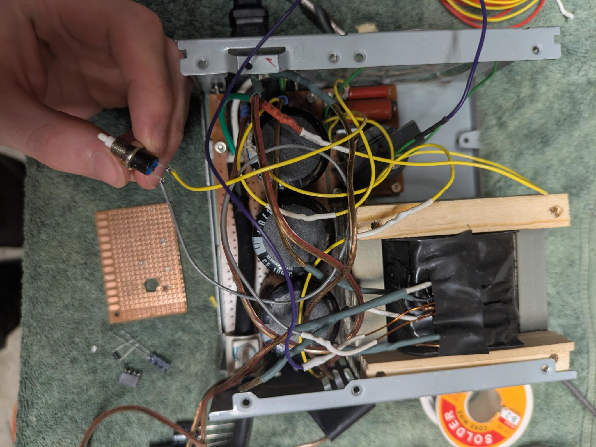
I chose to use the box from the computer power supply I took apart to house the flash lamp driver circuit. I 3D printed some pieces to help mount the circuit boards and ensure that any high voltage leads were not exposed. An optoisolator was used to switch the 1.1V AC from the single winding on the power transformer into the thyristor to flash the lamp, allowing the lamp to be safely triggered using GPIO output from a computer. I also added a push-button which would fire the lamp when pressed. The final assembly consisted of a plug for mains power to come in, a socket for the lamp to be attached, and two leads for a trigger signal to come in from a Raspberry Pi.
