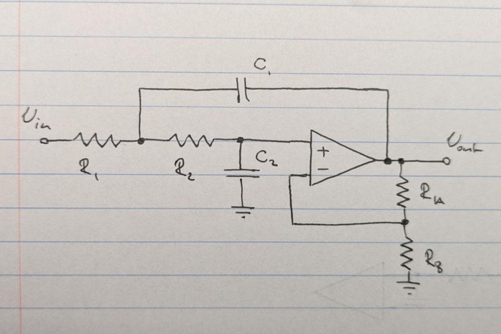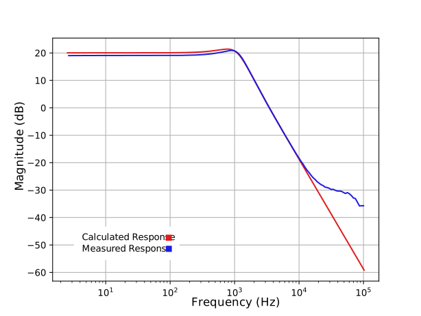
Fig 2. Sallen-Key filter frequency response
As a full discosure I ripped the schematic for this project right from the internet and did next to no schematic design myself.
Pictured below is the schematic of the guitar pedal (full schematic here).
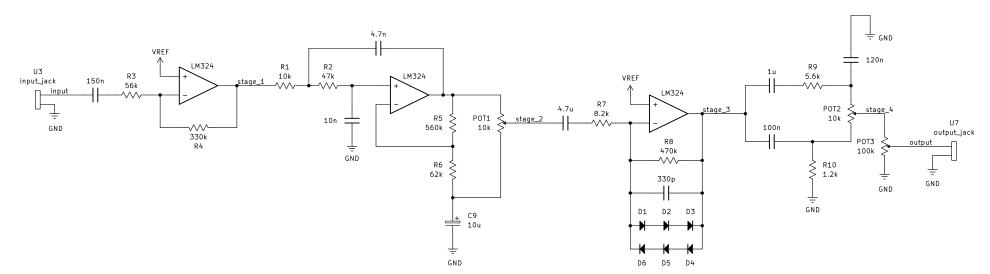
When the signal comes in it's first capacitively coupled in and brought through an inverting op-amp with a gain of 5.9. This stage also acts as a high pass filter with a cutoff frequency of 18.9hz, filtering out any signals that are too low frequency to be picked up by the human ear (most people hear ~20Hz-20kHz).
The signal then enteres a Sallen-Key low pass filter with the transfer function shown above (with values corresponding the labeled schematic here). It has two complex poles at s=-3292±5867i, for a natural frequency of ω=6728, and damping ratio of ζ=0.489. This corresponds to a -3dB frequency of f=1375hz and a Q factor of Q=1.02. A 10uF electrolytic capacitor acts as a virtual ground, charging to the average voltage of the input signal and holding there relatively constantly with a time constant through the resistor network of about 100ms. The voltage divider between the op-amp output and the 10uF capacitor causes the Sallen-Key filter itself to have a gain of about 10. The potentiometer then acts as a voltage divider on the output to bring the gain back down to something lower.
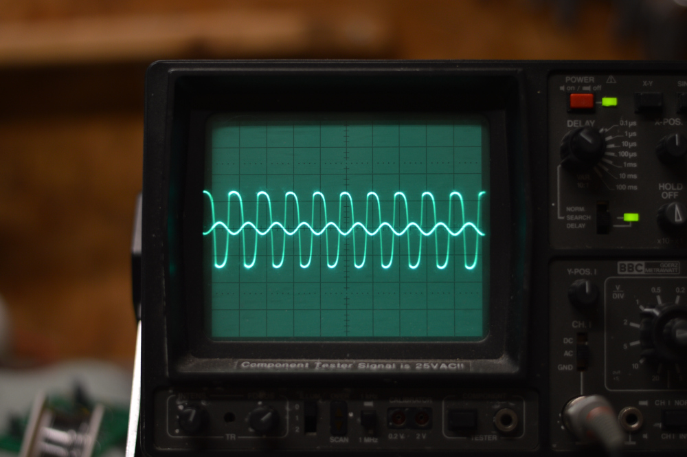
The next stage is where clipping of the sound wave happens, which is what gives this pedal a lot of it's characteristic sound. This stage tries to act as an inverting op amp with a gain of about 60, until the diodes start to conduct, "squaring off" the waveform. This introduces a lot of higher odd harmonics as we're essentially changing the input into a square wave whose Fourier series contains odd harmonics with their amplitude decaying with the inverse of the frequency. I believe capacitor across the diodes acts as a low pass filter and is the reason the signal in figure 3 looks slightly skewed (doesn't exhibit quarter wave symmetry). The analysis gets a little weird for me here though, as there are significant nonlinear effects.
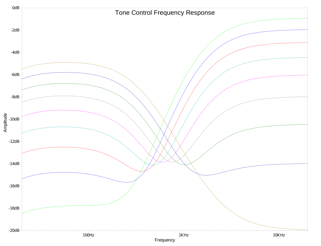
Finally, the signal enters the tone control section of the circuit. This part is essentially a high pass filter, a low pass filter, and a potentiometer to shift between the two. A simulation of the frequency response of the tone control for a variety of potentiometer positions pictured to the right (Fig 4.). The 1uF capacitor provides capacitive coupling and causes the slight roll-off seen in the frequency response. This should be pretty inaudable however as the lowest string on a guitar in standard tuning (low e) has a fundamental frequency of 81hz.
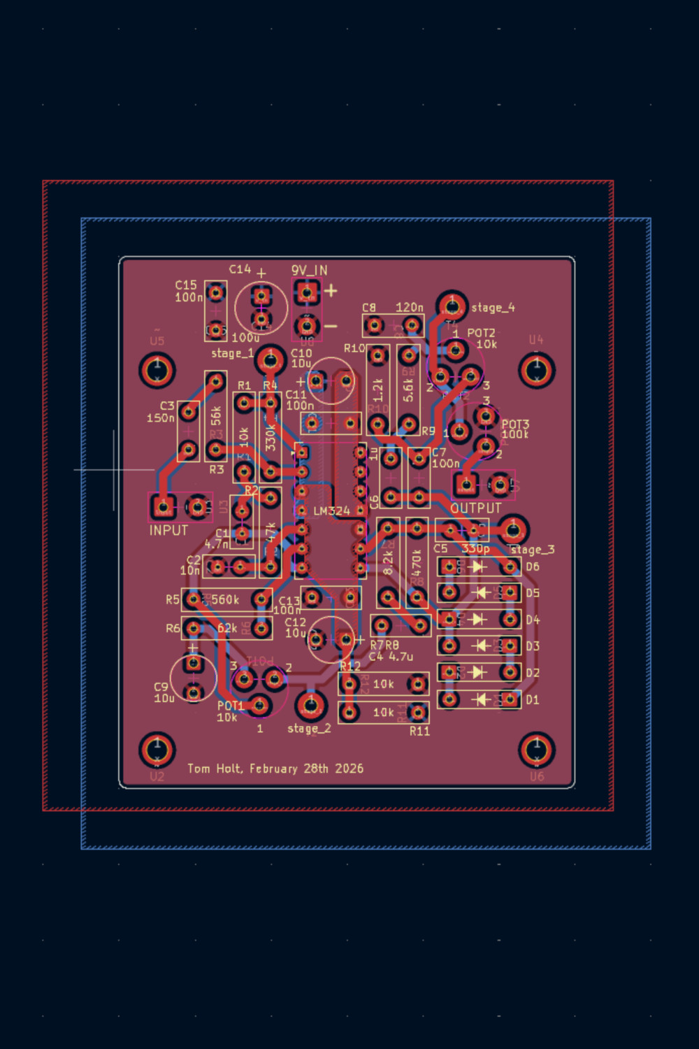
Pictured below is the layout of the PCB