One of the tasks in the UBC Engineering Physics robot competition involved detecting and picking up a 3D printed "rock" which contains aluminum foil and was visually identical to several other "rocks" on the course. My team wanted to be able to detect the rock as we drove by which required a quite sensitive metal detector. I ended up really enjoying designing this and I figured it warranted a page of its own.
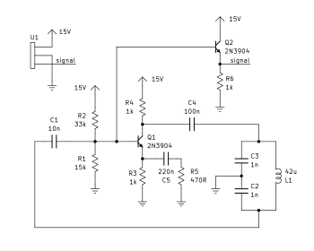
The general design I decided to go with uses a Colpitts oscillator, which consists of a common emmitter amplifier which drives an LC tank circuit. The inductor in the tank circuit is a large air cored coil. When metal is placed near this coil eddy currents in the metal oppose the magnetic field, resulting in less magnetic flux through the coil and this a lower inductance. This lower inductance results in a higher resonant frequency (at least for aluminum, sometimes ferromagnetic metals lower the frequeny as they amplify the field).
Most metal detectors that use Colpitts oscillators run in the range of 100kHz becuase the skin effect reduces their sensitivity at higher frequencies. Because this detector is being designed for aluminum foil specifically however, which has a thickness of a few tens of micrometres, we can achieve better performance by running at much higher frequencies than this. In order to be able to do this I designed a mixer circuit to generate the difference frequency between two oscillators so that this lower frequency could be fed into the ESP32 that our robot uses. This difference frequency changes just as much as the oscillator frequency but can be much lower and therefore easier to deal with.
The final design used two oscillators, with a coil on both the left and right sides of the robot to detect the rock on either side.
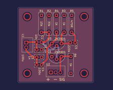
Pictured below is the final design of the oscialltors. They consist of a fairly standard Colpitts oscillator circuit, along with an emitter follow as a buffer to help drive the lower than optimal input impedance of the mixer circuit. The buffer was placed to take advantage of the biasing already in the circuit.
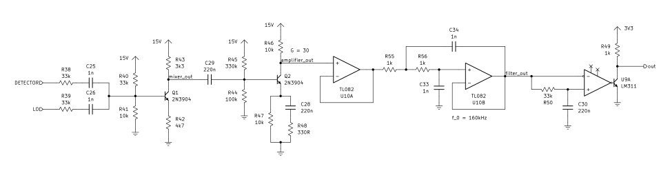
Pictured above is the schematic for the mixer I designed. The signals to be mixed are first added together and scaled down. Mixing occurs in transistor Q1. The PN junction between the base and the emitter has an exponential response as described by the Shockely diode equation. Viewing this exponential response as a Taylor series, the quadratic term results in the multiplication of the signals. The product of two sinusoids is composed of their sum and difference frequencies, the latter of which we aim to isolate. We also get several other frequency components such as the original signals themselves, which pass through via the linear term in the Taylor series, but these can be removed with filtering.
The next stage of the mixer is a common emitter amplifier to boost up the mixer output. We actually get a decent amount of filtering in this stage via the miller effect which turns out to be desirable in this case. After that the signal is buffered and then filtered by a unity gain Sallen-Key low pass with a cutoff frequency of 160kHz. Finnaly the signal is digitized with an open collector comparator using a low pass filter to hold the voltage at the non-inverting input to the average voltage of the signal.
The coils were wound around a 3D printed oval track designed to be as large as possible without getting in the way of the robot's mechanical components. They had an inductance of around 42μH
After some experimentation with capacitor values in the oscillator tank circuit I decided to go with a 1MHz oscilator frequency. This seemed to strike a good ballance between sensitivity and ease of use (at 3MHz the circuit functioned as a rather effective "hand detector" as bringing by hand near the circuit capacitively coupled me into it).
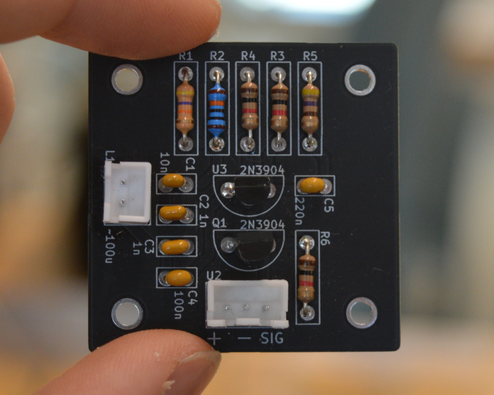
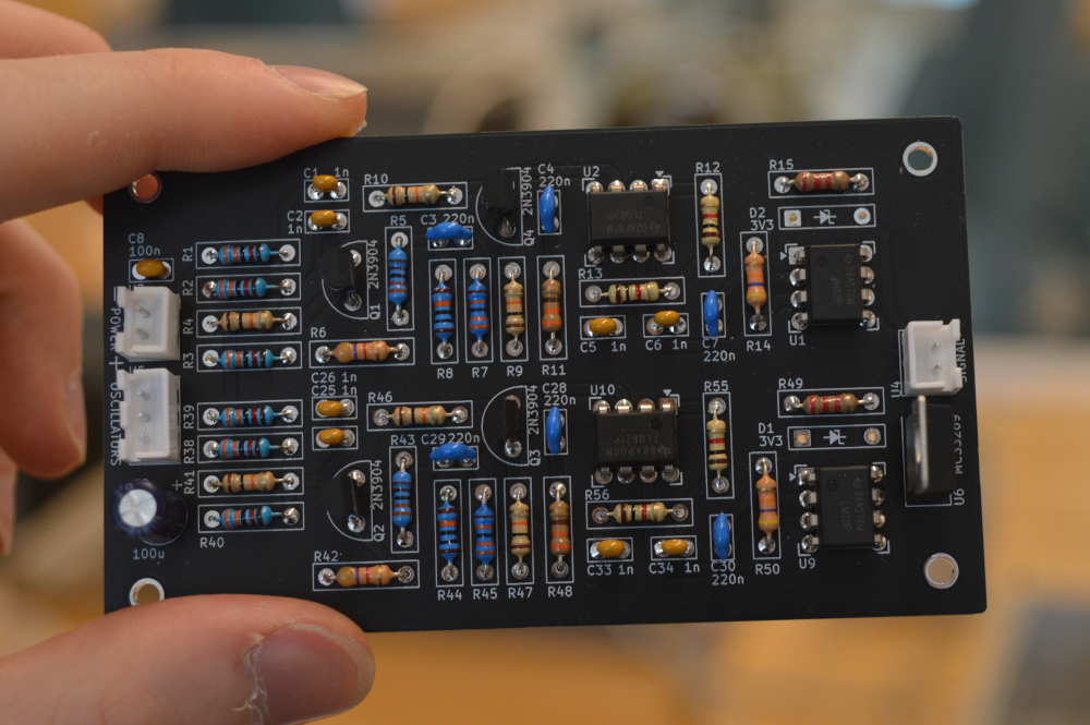
The mixer PCB has two mixers on it as I origianlly intented to have a metal detector oscillator on either side of the robot, and a stable reference oscillator to mix with both of them. Unfortunately however, when testing the mixer PCB I found that when both mixers were running at once there was considerable cross-talk between with would sometimes result in their outputs locking together or becomming chaotic. To get around this I decided to use only two oscillators, both functioning as metal detectors, and mix them on a single channel of the mixer. I tuned the one on the right side of the robot to a higher frequency with some aluminum tape near the coil so that if the mixer output frequency went up we would know the aluminum was on the right, and if it went down we'd know it was on the left. It seemed like the cross-talk was being coupled in through the ground plane so I believe it could have been aleviated by adding decoupling capacitors next to the amplifier and filter, and separating the ground and power planes for each mixer and connecting them with a net tie.
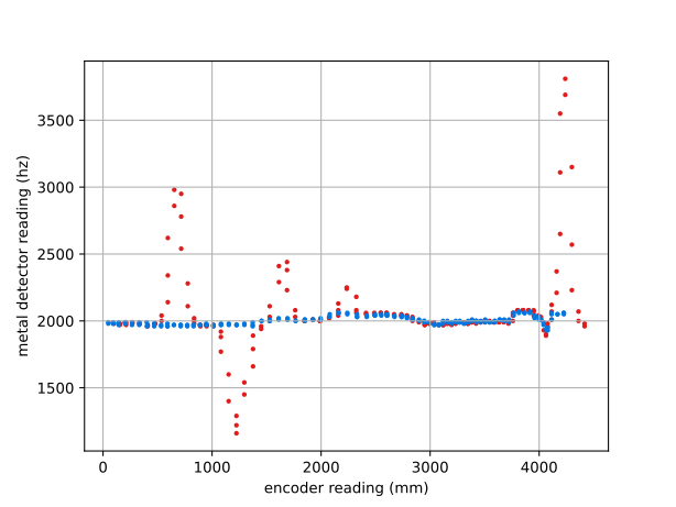
When we initially put the metal detector on the robot we had some issues with noise from the motors interfering with it. When the robot started to climb the ramp it would detect metal. To fix this we made three changes: moving the motor power wires further from the coils, adding 100nF capacitors across the motor leads to lower the frequency of ringing, and powering the mixer board with a seperate 9V battery with a shared ground to the rest of the robot. These hardware changes seemed to fix the issue as can be seen by the graph on the right which shows the metal detector readings vs. position, with position being calculated based off encoder readings from the driven motors. The blue dots are a run with no rocks and the red ones are a run where every rock contains aluminum, which causes the spikes in the graph. I'm not sure which hardware change fixed the issue but if I had to guess it would be getting the mixer it's own power supply seeing as the cross talk observed earlier suggests it's very sensitive to noise in the ground and power planes.
The firmware for metal detecting used PCNT to count rising edges on the metal detector signal pin in a 100ms sampling period and calculate a frequency based off that data. The frequency data was then put through a discretized high pass filter with a time constant of 10s to try and mitigate false positives caused by oscillator drift. The filter output was then compared with a threshold of 200hz; if it exceeded +200 it would detect a rock on the right, and -200 would detect a rock on the left. With such a setup we were able to reliably detect metal with a range exceeding 20cm and reliably find every rock on the course.