As part of my program at school, the summer after second year students compete in an anual competition in teams of four to build a fully autonomous robot. I was recently one of these students with our competition in my year being mars habitat themed (learn more about rules here). I ended up doing a bunch of electrical design for our robot.
The goal of the competition is to score as many points as possible by completing tasks. The tasks were removing the cover of a solar pannel for 2 points, retrieving a metal containing 3D printed "rock" for 2 points, detecting teletubby figurenes and flashing a light for 2 points, assembling a 3 piece 3D printed "radio tower" for one point for each piece assembled, and assembing a 4 piece 3D printed "habitat", again for one point for each piece assembled. The competition surface was 8x8 feet, made of plywood, with a ramp in the middle. It had an electrical tape line that could be followed by sensing the reflectance of the ground to help navigate the course.
My team decided to focus on detecting the telletubbies, removing the solar pannel cover, retrieving the rock, and assembling the tower.
To follow the electrical tape line I made a circuit with two infrared LEDs to shine IR light at the fround, and two phototransistors to pick up the reflectance of the surface. I soldered this circuit on some perf board for initial testing, and then made a PCB for the final robot. The signal from the phototransistors would then be sent to our ESP32s, and would be used to get an error signal for how far from the line the robot is. One of my teammates wrote a program to use PD control to throttle the H-bridges, and ensure that our robot remained on the line.
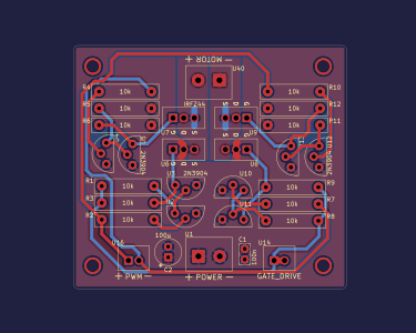
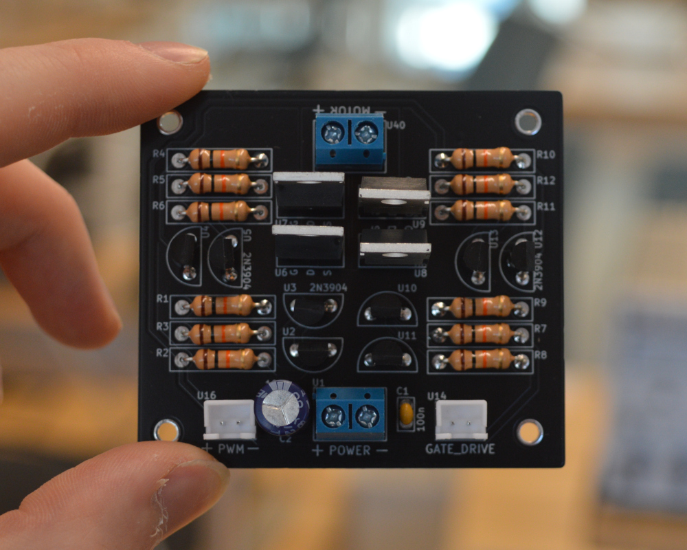
Here are the H-bridges I designed for my team to use to control our DC motors. When routing the board I tried to avoid cutting the power planes with traces to allow the H-bridges to supply as much current as possible.
One of the tasks in the competition was to remove the cover of a solar pannel. The solar pannel had an infrared beacon above it that would flash at either 1kHz, or 10kHz (to avoid interference between beacons on different competition surfaces), and could be used to help find the solar pannels. Pictured below is a board I designed to pick up the signal from the IR beacon, filter it, and send it to our ESP32 for further processing.
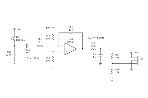
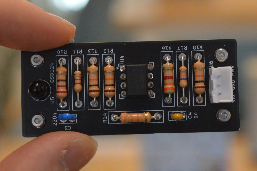
The signal for this board is generated using a phototransistor aimed at the beacon. The phototransistors provided had considerable parasitic capacitance so a small resistor was used in series with it to reduce the time constant and allow the voltage of the signal to have a higher slew rate. The signal then is capacitively coupled into a inverting op amp wit a gain of ~7. This section also acts as a high pass filter with a cutoff frequency of 154hz, removing signal components much lower than the beacon frequency. The signal then enters a low pass filter with a cutoff frequency of 48.2kHz, this time to remove signal components much higher than the beacon frequency. A voltage divided is then used to decrease the amplitude of the output signal to ensure it never exceeds the voltage rating of the ESP32 (this board is powered from our ~16V battery).
Once the signal enters the esp32 it can be cross-correlated with either a 1kHz sinusoid, or a 10kHz sinusoid, using a program written by one of my teammates. We used both an inline and quadrature wave and combined the results with pythagorean theorem so that we wouldn't get any issues caused by phase. Larger magnitudes of the cross correlation would tell us we were either closer to the beacon, or pointing more directly at it.
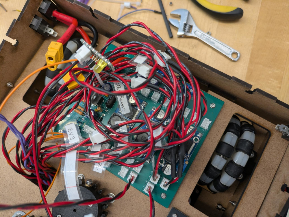
Various parts of our robot required different voltages in order to function, for example the raspberry pi and ESP32s needed 5V, the MOSFET gates on the H-bridges needed 20V, the servos needed 7V, the line following boardeds needed 3V3, and the motors got their power directly from the batteries. I designed a PCB to route power to these various subsystems, with lots of connectors for each required voltage. I used external adjustable buck converters that were provided to us to supply the 7V, 5V and 3V3, and a boost converter to supply the MOSFET gate drive voltage. The boost converter used a 555 timer to generate the switching waveform for the MOSFET gate, and a voltage divider on the output with a comparator to disable the 555 timer once the voltage had reached the desired level for control. I used JST connectors for the relatively low current connections, and screw terminals for the power for the DC motors.
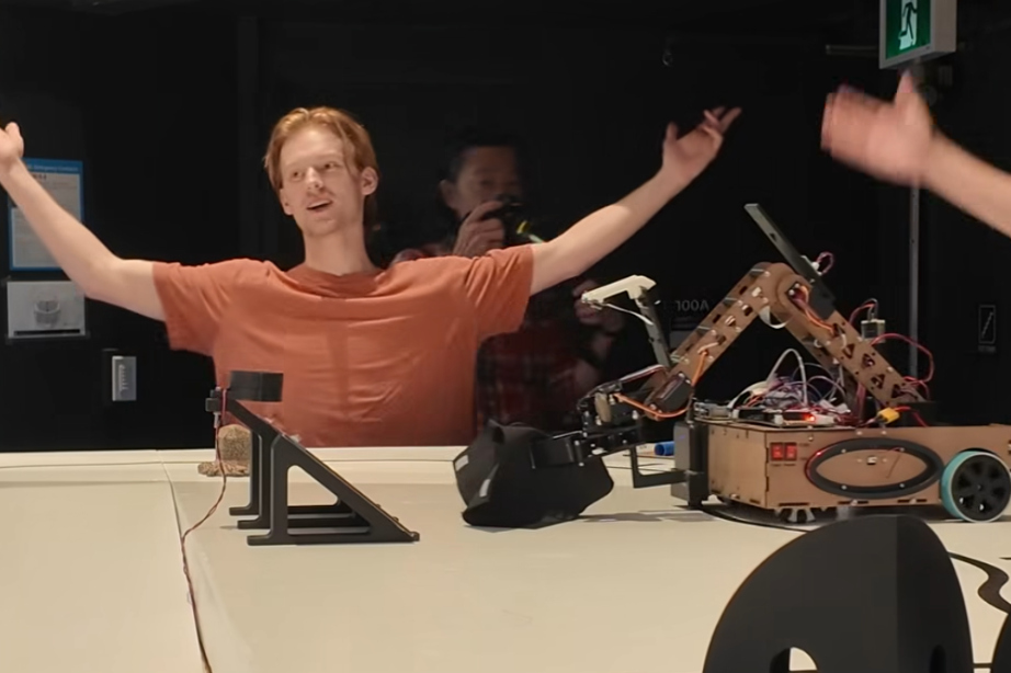
Pictured to the left is the final constructed robot my team and I designed, along with myself celebrating after our robot removed the solar pannel cover. We ended up tying for 7th out of 16 teams. We would've liked to do a bit better but one of our team members became very sick in the second half of the competition, and she was probably our most capable firmware writer, so our robot had rather janky code written pretty last minute. That considered, I think we did pretty well all things considered, and I'm very happy with the learning I got out of this competition, along with the fun I had.